


Prop-Shaft Driven Alternator
When Joshua Slocum sailed around the world in 1897 he had an oil lamp for light and navigation lights, a wood stove for heat and cooking, and a sextant and wind-up tin clock for navigation.
That was it. No GPS. No chartplotter. No autopilot. No fridge. No laptops. No CD player. No LED lights. No Watermaker. So he had no need for electricity.
But we do.
We like all our creature comforts, but it is a challenge keeping our batteries charged. Yes we have solar. Yes we have a wind generator, and they are both great. But if the wind doesn’t blow and, especially if we use the laptops a lot, or when we are on a long passage with night sailing, we can’t keep up and have to run our engine to charge things up again.
But maybe there is a better way!
Is A Propshaft Driven Water Generator the Answer?
Inspired by Dennis Glannon’s experiences with his Propshaft Alternator I decided to set about installing my own solution.
It involved a lot of thinking, hunting for parts and handing upside-down in the bilge trying to figure where things would go, and it also went through several iterations. My hope is that this account will make the journey easier if you decide to go this route.
First Iteration
At this stage of the game our boat was powered by 600 Ah of AGM batteries that were at least 10 years old. We were also using a 15 x 15 fixed blade propeller. Both of these facts are significant, as you will read later on.
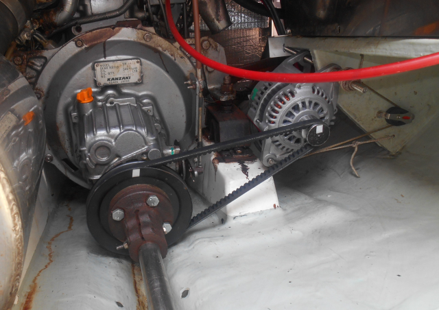
Here is a picture of our first installation:
How Much Power Did it Produce?
Power production started at about 5kts. At 6kts we were at maximum output voltage, which is 13.5v with this alternator and its internal regulator. With a 90% charged battery, that was giving me about 8amps. The high starting point (5kts) is due to the gear ratio which I will discuss below. Even so, that is some handy power once we pick up some speed.
Installation Considerations.
The first thing, of course, is that you need to have a prop that is happy to freewheel. That means that you need a gearbox that is happy to have the prop freewheeling. We have a Yanmar 3JH3E with a Kanzaki KM3A1 gearbox that is specifically designed for freewheeling. Some gearboxes are not – check and make sure before you install your own system.
Second, you need to have room to install a pulley on the propshaft, and an alternator in line with it. Now, the key thing is to have as large a pulley on the propshaft as you can manage. Dennis managed a 10 inch wheel. We had space for only a 6.5 inch pulley that we bought from a local auto-parts (and other hardware) store. It is made of welded steel plates, making it nice and thin and flat. A local machine shop was able to drill the holes in it so that I could easily install it between our prop coupler and torque limiter (cost about $90 in Canada).
Then you need a small pulley on the alternator. Now, the key thing is the ratio between the two pulleys. The goals are:
- When the propshaft is rotating at its maximum velocity (most likely when surfing down waves in a gale) the speed of rotation at the alternator end does not exceed the alternator’s maximum rated speed.
- At the same time, you want to get into the productive speed for the alternator as soon a possible when sailing at slow speeds.
- But, you need enough torque coming from the rotating blades to be able to turn the alternator and produce power. Try to turn it too fast with too little torque, and it just won’t work – the props will just stall.
- Finally, as a check on the above, make sure that when you are motoring at maximum revs the prop shaft is not driving the alternator too fast.
Ok, so how fast does the prop rotate when sailing? That is the rub, and is hard to guess. However, what you CAN do is to buy a simple laser tachometer and actually measure it! Alternatively, you can calculate the theoretical maximum using the following formula:
Max RPM = speed in knots x number of inches in a nautical mile (72,913.38) / (60 minutes in an hour x pitch of prop in inches )eg, for us at 13 kts with a 15 inch pitch on our props the theoretical max rpm is 13 x 72913/(60 x 15) = 1053.
Motoring at 3300 rpm with a gearbox ratio of 2.64 gives us a max prop speed of 1250. The max speed for my alternator is 18,000 so I could go up to a 14:1 ratio and still be safe! With the 4.3:1 ratio that I have, my max alternator speed will be 5,375 rpm, which just gets me to the ideal speed for this alternator.
To measure the RPM use a laser tachometer. Stick the short pieces of reflective tape onto the two sheaves. Make sure the rest of the surface is dark and non reflective. For my alternator sheave I painted black marker pen all over it except for where the reflective tape lies. You can see the little white squares in the photo, one on each of the pulley sheaves. Then just aim your laser at the pulley, and read off the RPM.
My actual measurements for my 15″ by 15″ three bladed fixed prop were thus:
| Boat Speed | Prop RPM (freewheeling) | Prop RPM (alternator ON) | Alternator RPM (alternator ON) |
|---|---|---|---|
| 4kt | 206 | 133 | 450 |
| 5kt | 260 | 177 | 955 (almost no power being generated) |
| 6kt | 323 | 314 | 1052 (good power now being produced) |
You can see that the prop speed drops once we turn on the alternator and extract some power from it, but that the amount it drops decreases as the speed (and thus available water power) increases. At higher speeds there is probably only minimal drop in speed, and with that, minimal effect on our speed through the water.
From my calculations I figured I needed as high a ratio as I could get. 6:1 would probably have been ideal but, unfortunately, as you can see from the photo, there was space only for a 6.5″ pulley, and thus 4.3 was the highest ratio I could achieve. If you can, try to go higher. However, be aware that if you go too high, you may just stall the props and thus get no power at all.
To achieve that ratio requires having as small a pulley as possible on the alternator. And here is the challenge. The shaft on my alternator is 17mm. The smallest pulley I could find was a 1.5″ aluminum die cast sheave from Chicago Die Casting, which had a 12mm hole. I had a machinist drill and thread the hole in it to fit on the alternator but, alas, it was not strong enough.
That meant I had to have a special sheave made for me, which cost 60 Euro in Turkey. If you go that route, make sure that the V is cut deep enough. When you install it, put some red marker pen on the inside of the V and make sure that in the depths of the V it does not get rubbed off by the belt. If it does, it means your belt is touching the bottom, and you will have problems.
You can see the broken die cast sheave and the new stainless steel sheave below. Note the hole for the grub screw to make sure the sheave does not come off the alternator when the engine is in reverse.
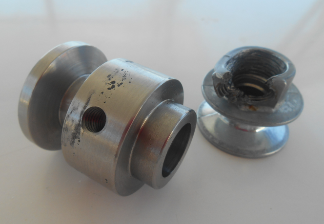
The sheave on the right was cast aluminum – and clearly not strong enough for the job.
Again, if you can fit a huge pulley sheave like the 10″ sheave that Dennis has, you can then go for a bigger sheave on the alternator (perhaps even using the standard one), which reduces stress on the system considerably.
Initially I tried to find notched timing belt pulleys and multi-V pulleys (as used in modern serpentine car fan belt systems) as both of these need less belt tension that a traditional V belt, but I could not find them in the right sizes, so I had to go with the classic V in the end. Because my alternator pulley is so small I also made sure that I used a high quality notched belt, as they are more flexible.
To do your pulley and belt-length calculations, there is an excellent pulley calculator available on the net.
You will see in my installation that I simply used a piece of nylon string to apply the belt tension. The string was attached to the side of the hull. As you will see below, this is not the way to do it. Make 100% sure that the bolt on which you are hanging the alternator is exactly parallel with the propshaft in all 3 dimensions. Put a straight edge across the front of the alternator sheave and make sure that it runs parallel with the fan belt. Make sure the fan belt sits straight in both sheaves and that their is no twist. Then run your engine to spin the alternator and check if any black dust appears. Do this several times when you first install it, and check it at intervals. If you see any black dust, it means your belt is rubbing, which means either it is not aligned correctly, or it is slipping and needs more tension. Fix it, or it will soon be garbage. Be aware also that if there is any rubbing, your belt, and the offending sheave, will be HOT (don’t ask how I know that). Don’t burn yourself .
Make sure also that the alternator spins the right direction. In most cases the alternator spins clockwise (as you face the spindle) and your props also rotate clockwise (as you look forward) which means that you have to install your alternator facing backwards as I have done.
What Alternator to Use?
Dennis advocates a small output alternator. That made no sense to me so I used an Hitachi LR160-741, which is the standard 60amp alternator that Yanmar supplies for my engine. I bought it as a spare, so it was lying around unused. It has an internal regulator which means that I cannot adjust that, nor can I install a smart regulator such as the ones from Sterling Power. No matter, it still works. You could use your old one that you replaced with your new high-output alternator. Or find a used one from a car wreckers. Get one with an external regulator.
Try to find an output curve for your alternator before you buy it. Below is the curve for the Hitachi LR160-741. Note that power output begins at just 1000 rpm, though power at that speed is minimal. In setting up your system, aim to get to that 1000 rpm for as low a boat speed as you can, while still keeping the upper end within the maximum permitted speed. In practice you won’t get any power from less than 4kts anyway, as the prop won’t even be spinning because of too much friction in the bearings. But once you get to 5kts it would be nice to be well into the power band. Unfortunately with only a 4.3:1 ratio I can’t quite achieve that.
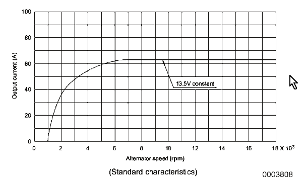
Hitachi LR160-741 Output Curve
Parameter Yanmar Code 128271-77200
Alternator Model LR160-741 (Hitachi)
IC Regulator Model SA-A (Hitachi) 12 V
Battery Voltage 12 V
Nominal Output 60A
Earth Polarity Negative Earth
Direction of Rotation (Viewed from Pulley End) Clockwise
Weight 4.2 kg (9.2 lb)
Rated Speed 5000 rpm
Operating Speed 1050 – 18,000 rpm
Speed for 13.5 V at 20°C (68°F) 5000 rpm
Output Current for 13.5 V 56A or more at 5000 rpm
So, at low boat speeds you start to get a little power. As your speed increases, and the available water power (which increases at the square of the boat speed) increases, you will move along to the right on the power curve and thus be able to produce more power. Remember that even at its maximum, a 60amp alternator is, after all the inefficiencies in the system, only pulling at most about 4hp from your props. Now consider how much power it takes to get your boat moving at 8kts and you will see there is more than enough power available from the water to produce a good output.
How much will it slow your boat down? Again, at MAXIMUM power (ie when you are going really fast anyway) it would be the equivalent of attaching to your boat a small 4hp outboard pointing the wrong direction. You probably won’t notice anything, unless you really are racing. Most of the time your draw is going to be way less than 1hp.
The next challenge was to identify the alternator terminals. After much hunting I managed to do that as shown below:
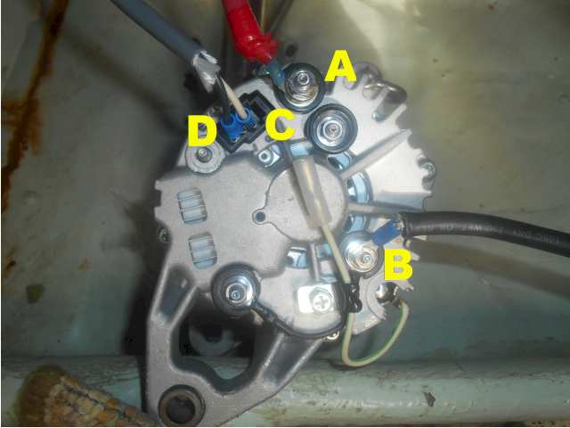
Hitachi LR160-741 alternator terminal connections
| Terminal | Purpose |
|---|---|
| A | Battery Positive |
| B | Battery Negative (isolated ground) |
| C | Excitation/Lamp lead or ‘L’ |
| D | Voltage Sensor or ‘R’ |
The battery positive and negative are, of course, attached to big fat cables that go to the battery terminals. Make sure that you install an inline fuse on the positive cable. An isolated ground means that the casing is not attached to the negative terminal. Not all alternators have that feature, for most the casing acts as the battery negative. The benefit is that the entire current does not flow through the engine block but, instead, flows through the fat cable directly to the battery. Remember, NEVER disconnect either of the battery cables while the alternator is spinning – you will blow the diodes and kill your alternator.
I did not connect the Voltage Sensor to anything. The regulator already has a built in sensor. However, if you are using a splitting diode to separate your house and starter batteries, the sensor should be attached to the house battery side of the diode, otherwise you will lose power because of the voltage drop across the diodes. Note again, that if you do use the sensor, it too should have a switch to turn it off when not in use, or else you will lose a small amount of current through the whole system when it is at idle.
I took a long wire from the engine room to my dashboard panel. There I installed an on-off switch and a car-reversing beeper before taking the wire through a fuse or circuit breaker to the positive bus bar. The end of the long wire in the engine room is attached to my Excitation lead. With the switch in the off position the alternator can spin as much as it likes, but it produces no power. Once I switch on the Excitation lead, the beeper will beep, the alternator field coil will be energized, and the alternator is now ready to generate power.
How to Operate Your New Water Generator.
When sailing at less than threshold speed (for me that means less than 5.5kts) keep the excitation switch OFF. If you turn it on, it will beep at you and you will actually see that current is flowing in the WRONG direction – ie you are using up amps instead of generating them.
Once you reach the threshold speed, switch the excitation on. It should beep briefly, and then the beep should either stop completely, or go much quieter. You should then see some positive current coming from your alternator. You can measure that directly by putting a clamp meter around the batter cable, or by comparing you battery charging current now with when the switch was off.
If your speed drops, the excitation will start to beep again. You should then turn if off, or you will lose current again.
If you start the engine and you did your calculations correctly, you should be able to safely switch or leave the system on and boost your charging. Now you have two alternators instead of one.
If you go in reverse, you should turn it off so as to minimize the load on the alternator. Most alternators are not designed to run in reverse for three reasons:
- The cooling fan works only one way. Run it backwards and it will soon overheat. Turning off the excite switch solves that.
- The brushes are often aligned at an angle and may jam if it rotates the wrong way. If you have a choice about what alternator to use, try to get one with straight brushes.
- The sheave might unscrew and fall off (though that is why you have a grub screw on it). Again, by not putting any load on it, this will be minimized
Maintenance
The system should be pretty maintenance free. Check every now and then for belt tension and any tell-tale signs of black dust.
First Problem
From the above it would seem that our system was working well. Indeed it was, in that it was producing a nice amount of power when we were going fast enough.
BUT, the method I used to tension the fan belt, ie by pulling the alternator sideways to the side of the hull, was putting undue sideways tension on the engine mounts. The result was that the engine was actually being pulled sideways, thus putting the propshaft out of alignment. That is not a good idea.
So at that point I dismantled the system. What was needed was a way to brace the alternator and tension the fan belt while keeping everything attached to the motor itself so that there is no resultant sideways force on the mountings.
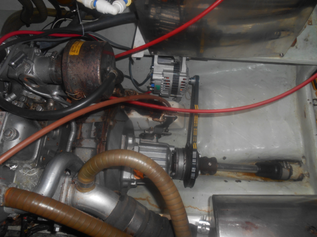
Second Iteration
Since installing, and then dismantling, the first iteration we have made some upgrades to the boat. Specifically we have now installed brand new Lithium Ion (LiFePO4) batteries and a pair of FlexOFold 16 x 13 3-blade folding propellers.
Having done all that, I finally found time to work on the water generator again. This time I managed to find a way to tension the fan belt by pushing it sideways with a strut mounted on the transmission case, rather than pulling it sideways to the side of the hull. This, I figured, would put a lot less stress on the whole system.
Having once again wired it all up we were ready to go and test it. Note that since we have folding props they would not normally be rotating as we sail along. However, if we get them rotating by a bit of engine for just a second, they will then continue to rotate by force of water until we actually stop them, for example by putting the stopped engine into gear. That then stops the prop, they fold up, and they then won’t spin again until we get them going again with the engine. That is not a major issue, it just means we have to kick start them with the engine any time we want to use them to drive the alternator.
Here are our prop speeds this time:
| Boat Speed | Prop RPM (freewheeling) | Prop RPM (alternator ON) | Alternator RPM (alternator ON) |
|---|---|---|---|
| 4kt | 225 | 0 | 0 |
| 5kt | 320 | 0 | 0 |
| 6kt | 370 | 0 | 0 |
First, we can see that the prop is spinning quite a bit faster than it was when we had the 15 x 15 prop. This is to be expected because with the smaller pitch the new prop has to go faster to cover the same distance. In fact the new theoretical max rpm for this prop is now 13 x 72913/(60 x 13) = 1215 compared with 1053 for the old prop, both at 13kts through the water. That is a 20% theoretical increase and it seems to be borne out by our experimental results of about 15% increase.
BUT, the other problem we have is that as soon as we turned the alternator on, the props stopped! So what happened?
Second Problem
With the smaller pitch, the props spin faster than they did before. That means that we also have less torque coming from them. However, at 6kts I am sure there is still quite a bit of power coming through them. That in itself would appear to be insufficient explanation for them stalling.
But the other change we made was the new lithium batteries. One thing we have noticed with these batteries is how much quicker they charge. At 90% charge the old AGM’s would never accept more than about 15 amps even when running our high output alternators on our engines. But at 90% on the Lithiums we are regularly getting 35 – 40 amps from the same alternator.
When we tested the new setup by running the engines in gear at idle (under 1000 rpm) we were producing about 25 amps! 1000 rpm engine speed equates to 378 rpm prop speed. Which is basically what we were getting on our freewheeling prop at 6kts.
So here is what was happening. We would be freewheeling at 370 rpm. We switch on the alternator. It immediately attempts to deliver 25 amps to the batteries. But that is a huge power draw, and clearly was enough to instantly stall the props. At that point the props folded up and that was that. No power.
With fixed props it may be that they would still continue to rotate at a much slower speed, which would be further down the power curve on the alternator. Since they don’t fold up, they would find an equilibrium speed where the power output of the alternator would match what was available from the props.
Third Iteration?
To fix this problem it looks like we would need to decrease further the prop/alternator pulley ratio, perhaps by putting back the original larger sheave onto the alternator. This would rotate the alternator at a slower speed, thus producing and drawing less power and, perhaps, allowing the props to continue to spin. We still need the props to spin at a good speed so that they don’t fold up.
However, with our current set up I was unable to get the fan belt on and still tension it properly. Either I need a new, slightly longer, belt, or I need to rebuild the brackets for the alternator. Both entail a lot more work.
At this point I decided to abandon the project. With our new batteries we seem to be much more self sufficient with power, probably because they charge up so much more efficiently during the day, that the need for additional power is less acute. In fact, almost every day we are back up at 100% charge, often well before the end of daylight.
Conclusions
So, does a propshaft driven alternator work? Yes, but clearly there are a number of factors that have to work together to make it work.
Should you install one? That, again, depends on various factors.
It may be easier and cheaper to just add some more solar panels. In my case that would have been expensive, as I would have had to make alterations to the stainless steel frame and upgraded my MPPT solar regulator. And I already had a handy alternator that I could use.
Wind power is another option but, frankly, I think that the water generator is probably more cost effective, and less obtrusive. But the wind generator will work at anchor, while the prop shaft generator won’t.
Then, of course, do you have a freewheeling prop (preferably fixed blades), the space, and a convenient place to mount the alternator? Can you find a way to mount the alternator so that it is attached only to the engine, and not to any items that are outside of the engine mounts?
Can you fit in a big enough pulley on the prop shaft to give you a good ratio to your alternator? The ratio need for this depends on your prop pitch and the output curve of your alternator and battery combination. A smaller prop pitch means it spins faster, so you can do with less ratio. But probably the biggest issue is how much power the alternator will actually extract from the props. That depends on four things:
- the size of the alternator (obviously a bigger one needs more power to drive it),
- the ability of the batteries to accept charge (lead batteries accept little charge, whereas Lithium accept a lot),
- the regulator – a smart external regulator will try to deliver more charge, and thus puts more demand on your props
- the output curve of the alternator – how much does it produce at what speed?
With our old AGM’s and a fixed prop, we were getting good output at 6kts. Perhaps with a 6:1 ratio we would have had even more power at a lower speed. Or maybe it would have stalled. With the new Lithiums (and folding props with smaller pitch) it all proved too much even with the 4:1 ratio. We probably need a smaller ratio, and perhaps even a smaller alternator.
And, the biggest question is, “Do you sail enough?” If you spend your life at anchor or in a marina, this won’t do you much good!
In my opinion this is a great and easy way to get some extra free power, but it does take quite a bit of thinking and experimenting to get it to all come together.
Great detailed article. Found it when looking for Ideas for prop alternator on my new boat. I did a lot of experimenting when I fitted an alternator to the shaft of my last boat.
Three points I would like to make about your article:
1/ The alternator choice is actually very important. The alternator that you had on hand gets most of it’s field current from an extra set of diodes (3) attached to the stator windings; This means that the alternator can not stall itself because when it slows down there is automatically less field current (proportional to RPM). This is common to most Bosch alternators, you can recognize them from the lamp terminal which supplies a small amount of current to the rotor to get things going (as well as indicating a charging fault). Many alternators do not work this way and would stall the prop unless they were very small as Dennis recommends.
2/ An external regulator would stall the prop. An alternator can not stall a car engine, but it can stall a sailboat prop if driven too hard. An external regulator will try to drive the alternator to max current till it reaches it’s set point, with a big enough alternator, this will stall the prop.
3/ You would probably get higher charging voltage if you attached the voltage sense wire. Without it, the alternator regulator is sensing battery voltage through the current carrying leads; The resistance of the wires and connections will always make the battery appear to be at a higher voltage than it really is (I^2R). The sense wire can be small, it caries almost no current and eliminates this problem.
Cheers,
JM.
A well documented article on a good subject. Thank you!
I have read about shaft alternators earlier, but have steered away from them in fear of creating that sideways pull you mention. Do you by any chance have a picture or an illustration of the setup where you were able to counter the sideways forces on the prop shaft? If, so I would be more than happy to see it.
Greetings,
Petter
Very interesting article!
Did you ever consider to use a “LOW WIND PMA FOR WIND GENERATOR”, a Permanen Magnet Alternator made to produce a lot of electricity at low wind speeds (or should I say “when slow rotating”?). This in combination with a MPPT solar charge controller?
https://www.hurricanewindpower.com/permanent-magnet-alternator-low-wind-pma-rpm/
On the botthom of the page you find an table with the output at various alternator RPMs.
With this alternator a 1:1 reduction might be already OK and it will never overspeed the alternator even when the engine is on full rpm (gearbox about 1:3?).
Brgds,
Koen.
I didn’t, but as you say, it might well do the job.
This project was an interesting challenge. But, since most of the time we are at anchor or just day-sailing and are thus pretty self-sufficient in power already, this was not a project I wanted to spend a lot of money on. I had a spare alternator, so it seemed like a fairly cheap challenge. As it turns out, with the folding props this is now a non-starter, and so I have shelved it. But, sure, if you are starting from scratch low speed alternator would be a good option.
Don’t know if you have already dismantled your setup, but one thing you might try is to lower the current in your excitation circuit.
You say that you are using a “car-reversing beeper”, I imagine it’s a piezo-electric type that would already be quite low power, but maybe not ?
To lower the current you would need a lower wattage device, or to add some resistance in series with the existing device.
Hi John,
That is an interesting idea – the idea being that a smaller excitation would result in a smaller initial power draw, and thus might not stall the props, instead just slowing them down a bit.
Might work, but would require some kin of variable current control to experiment with it.
But I have indeed dismantled the arrangement. But a good idea for someone else to try.
Noel
Hi
Interesting.
I have 10 inch pulley on prop shaft and had an alternator with small pulley attached situated above the gearbox . It sort of worked but had to have good boat speed.
Tried putting resistors in to excite the alternator to start a lower revs .couldn’t get it to work and be of much use.
however I am about to fit a new gearbox that is good to free wheel so am going to have another crack at it.
I think I will fit a permanent magnet alternator that will start producing current at low revs possibly with a 12 volt clutch that will engage when power is applied. coupled to rectifier
I believe this is similar to the air con units on cars.
We are circumnavigating so we do a lot of miles at night down wind so the wind turbine doesn’t do much. the solar is good but doesn’t cope altogether we end up running the engine for short periods at night. it seams we have more amps going out than coming in .Auto Pilot 5 amps ish freezer 3 amps fridge 2 amps laptop 3 amps charging phones AIS inreach etc on and on.
I would be interested to hear from anyone who has tried this .